Introductions to Shaders for Digital Artists
A guide through the rendering process and getting started with Unity's Shader graph.
A lot of video game technical art is notoriously tedious – rigging models for animation, skinning weights, and of course modeling and animation themselves. These can take weeks of labor to complete just for one character or asset! But you also have a superpower at your disposal – one you may have not even realized it yet. This power is called a shader! Shaders are specialized computer programs that tell your graphics card how to color and display individual pixels or vertices of polygons.
Shader programs are one of the quickest yet most effective ways to express the visual design of your game. This article will teach you the high-level basics about shaders for video games and guide you through some short activities to get familiar with graphics-oriented thinking.
By the end of this article, you will be able to:
Decide if shaders are something you are interested in diving more deeply into
Learn more about how games turn geometry into a rendered frame
Use Unity’s Shader Graph and begin experimenting with it on your own
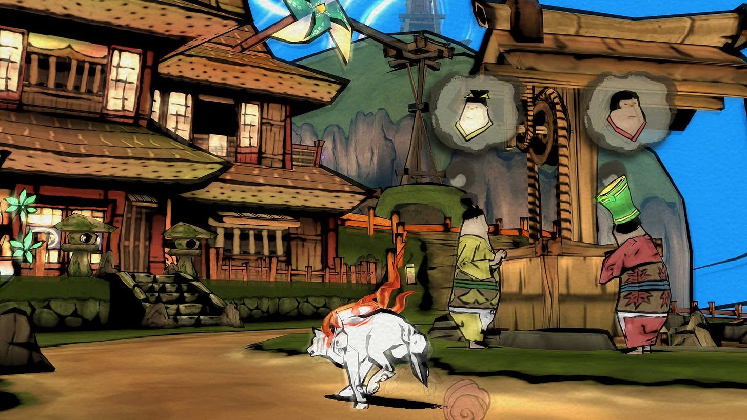
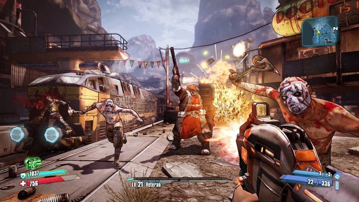
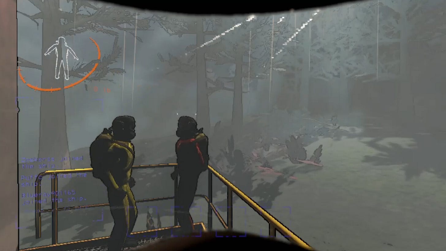
Shader programs are part of every game and every game engine, even if it may seem like everything is in the art assets or there are no computer-generated effects. Learning how to use them can elevate your game’s aesthetics and even reduce the work for other artists. Some of the most recognizable games in our field (like the ones pictured here) get their unique style from the combination of shaders and artistic direction.

Shaders can be used to create visual effects for individual objects or entire scenes, and the best part is that the hardware does all of the work! Shaders are similar to filters in creative applications like Photoshop or ProCreate, but are written using code and math that allows effects to be applied on-the-fly to anything in your game. If the mention of coding and math made you shudder, don’t fret! There are a few simple concepts to grasp and a lot of visualization tools to help you out. We will be doing our short activities with Unity’s Shader Graph editor, and code will be provided if you’d like to see how it correlates.
How does a picture get on the screen?

To understand how games get images up on screen, we can break the process down into three primary steps – Application, Geometry, and Rasterization.
The Application stage has everything to do with your game itself. If the player moves around or moves the camera, it will likely impact what should be shown on screen. Game applications handle user input, collision detection, physics simulations, and the game mechanics.
The Geometry stage involves a lot of math to translate the location of objects in the game world in order to project them onto your screen. At this point, we ignore any geometry that would not otherwise fit on the screen. This step relies heavily on linear algebra and matrix operations, which I won’t detail here but will provide resources at the bottom of the page if you would like more information. Modern graphics cards have specialized hardware that lets them do these projections and calculations incredibly fast.
Rasterizing is the final step, and it involves translating a 3D scene to a 2D image that appears on your screen! Rasterizers figure out what color every pixel on the screen should be. There numerous factors that could contribute to a pixel’s color, including lighting, shadows, highlights, transparency, and more. It’s at this point where the order of the geometry matters. Graphics systems keep track of how close every piece of geometry is to the camera, and they try to only render the things that you are actually able to see.
All of the data that is required for the Geometry and Rasterizing steps are stored in “Materials”. Materials tell the graphics system how to render a particular piece of geometry, and are meant as a convenience to the developer for easy asset reuse. They can make a material and then slap it on any piece of geometry. Consider them to be very advanced “filters” for the geometry. Common material types include metallic, plastic, glowing effects, and rippling/shimmering effects.
Your computer is doing all of these operations 60 times a second, at minimum. We often take a lot of modern computational power for granted, but it’s really an incredible feat of engineering.
The Power of UVs
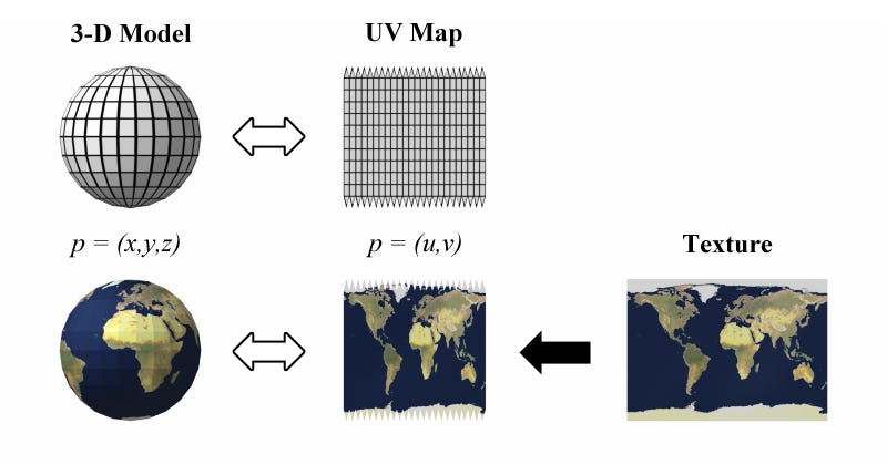
One of the core concepts that is fundamental to creating shaders is understanding UV mapping. You likely know that 3D models are initially just “unpainted” geometry, with no color or features. The intended look of the model (colors, clothing, visual details) are provided by textures that are 2D images. UV mapping is the process of projecting a 3D surface onto a 2D image for the purpose of assigning a part of a texture to a part of the geometry.
Now that we have information about particular geometry and how color maps onto it, we can manipulate the UV coordinates to create visual effects on the surface of the polygons. For example, we can have textures scroll over the surface to create things like simulated water flow, revealing different parts of the texture, and other color deformations. This allows us to do simple “animations” on the surfaces of geometry without having to change a texture or bake an animation. Here’s a good video that covers some examples of how much just manipulating UVs can accomplish:
To get you warmed up on the basics of manipulating UVs, let’s look at art tools that you are likely more familiar with already. Photoshop and ProCreate are designed to edit 2D images, and feature a variety of ways to manipulate those images including multiply, additive, and overlay filters. We can very easily accomplish these same effects in shaders by manipulating color on UV coordinates. Let’s do a short tutorial where we mimic the multiply color blend feature in Photoshop!
Activity 1: Flashing Lights
Let’s make a flashing light. This could be useful for an alarm light that rotates around, kind of like a lighthouse or old-school police siren.
Download Unity if you haven’t. Open Unity Hub, create a new 3D project that uses “URP”. URP is unity’s render pipeline. In other words, it’s Unity’s preferred engine for being able to do the three steps I outlined previously (Application, Geometry, Rasterization).
In the bottom Project panel, right click and create a new Shader Graph > URP > Unlit Shader Graph. Name it “BlendShader”.
Now right click the Project panel again and create a new Material named BlendMaterial. Double click to edit the Material and change the Shader at the top to your BlendShader.
Let’s create a 3D object so that you can see the effects of the shader on real geometry. Download the provided asset linked here and drag it into your Project window. Then drag it into the Unity scene. It should look pretty ugly and gray.
Drag the BlendMaterial onto the bulb part of the light model. Nothing should change yet.
6Now double click on the BlendShader asset to open the graph editor. You’ll see two nodes there named Vertex and Fragment. Those are the key to doing anything with shaders, and I’ll explain more in the next section.
In the WaveShader box on the left, click the + to add a float. Call it FlashSpeed and set it to 2 in the Node Settings tab. That box is how you add all kinds of variables that you can use in your shader program, and in our case we are using one to control the flashing rate. Now right click on the empty area in the graph, and you should see an option to add a node. This is the way to add many different operations and behaviors, which you will link by dragging the inputs from one node to the output of another. Add a Color node and make it any color you like (I picked Red). This will be the color of the light when it is on.
Now let’s make a way to have it flash. Two things we want to use are the game’s internal time and our FlashSpeed variable. Multiplying them together lets us change over time at a given speed.
Then let’s put it into a cosine function. I talk more about sine and other trigonometric functions in the next tutorial, but for our purposes it’s going to scale the amount of light up and down as time progresses.
We will multiply the output of the cosine wave with the initial color we chose. You should see it now flashing between black (off) and your color (on). This is the same operation as the multiply blend feature in Photoshop! But here we’ve been able to animate it a bit more.
In shader-land, where color is represented in a vector (R, G,B ,A), multiplying two color vectors is a way to combine their respective properties.
Speaking of animation, let’s apply our knowledge of UVs here to make the light actually spin around on the lightbulb. Using the Tiling and Offset node, we can shift where on the UV color should be applied.
Now go back to your scene view. You should now see the red spinning around on the surface of the light bulb!
On Your Own:
You now have a grasp on basic usage of the Unity shader graph and blending colors. This light is very basic and not very interesting. Plus, the fading between black and red looks a bit too artificial. Try stylizing the light a little more to your tastes, which could include:
Make the shader Emissive, so that it lights other objects in the scene
Blend the light to different colors, maybe another shade of red as it is warming up/down
Add highlights/glare to the “bright spot” of where a lightbulb would be
You may have to do a bit of external Googling to figure out how to apply some of these features, but these should be doable with only a few extra nodes.
Fragment vs Vertex Shaders
You may have heard mention of “vertex” and “fragment” or “pixel” shaders. What exactly do those mean? When should I use one over the other? In reality, you use both together, but for the purpose of understanding let’s look at them individually for a moment.
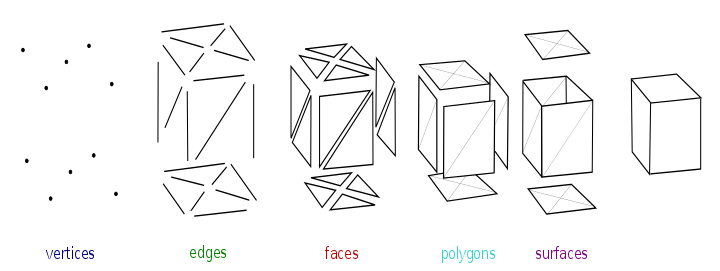
In 3D, you have three axes, X, Y, and Z which represent three directions in the world. In Unity, which is what we are using here, the Y axis is considered the “up” direction of the world and the Z axis is considered “forward”. Vertices are a way to represent a position in 3D space. You can connect multiple vertices to form edges, and then connect multiple edges to form faces. In computer land, we try to represent polygons with faces that are composed of tons of triangles. We’ve developed technology over the years that have allowed us to do calculations with these triangles blisteringly fast.
What a vertex shader does is allow us to manipulate these vertices. This in turn manipulates the edges, faces, and the overall look of the polygons. Vertex shaders can create slight distortion in shapes or geometry, like the effects of wind or animating buttons. Note that vertex shaders only affect the appearance of shapes and vertices, and won’t affect physics.
Now, what are pixels (sometimes called “fragments”)? Pixels are small bits of light and color that when combined with many other pixels form an image. The GPU needs a way to draw a 3D scene onto a 2D screen, and this is done through rasterization. Drawing tools like Illustrator or ProCreate do this same rasterizing process when they are trying to render your work to a 2D image. At this point, fragment shaders are run, which determine the color of the output pixel. There numerous factors that could contribute to a pixel’s color, including lighting, shadows, highlights, transparency, and more. These attributes are determined cheifly by the material being applied to the surface.
Pixel shaders also have the advantage of knowing information about the pixels nearby, which allows for cool tricks like toon shading, described below.
Common Shader Techniques
Here are a couple common techniques used for shading video games, which I attempt to explain with some of the knowledge you’ve gleamed so far.
Toon Shaders/Cel Shaders:
Toon shaders are often used in video games to evoke the look of comic books or cartoons. They feature less color blending and highlights, which make them look more “flat”. Toon shaders often include an outline around the edges of objects, again to mimic the outlines of a pen. They often recall drawing styles like Ligne claire, popularized by cartoonists in the mid-20th century,
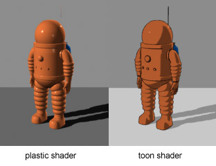
Under the hood, this is achieved by manipulation of the “Z-Buffer”, which is a way that graphics systems keep track of the depth of objects so it knows what will end up showing on top. The goal is to render only the things visible to the player and not hidden behind any other object. If you’ve ever played a game with a complex world and saw geometry flickering at intersections, this is likely the result of two objects fighting for the front of the buffer. For a toon shader, we color things slightly differently depending on how close or far they are from the camera’s view. In the above example, you can see how the parts of the spaceman angled towards the camera are darker than those angled away.
Noise:
Our world is full of randomness and imperfection, something that is hard for machines like computers to intrinsically understand. Noise allows us to add a little roughness to images, such that they appear more natural. There are various types of randomized computer algorithms used to generate noise, the most common type being Perlin noise. You can change the parameters of noise generation to encourage different generation behaviors, like more height variation.
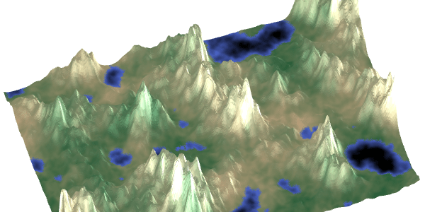
Noise functions are used in games for more than just graphics. Perlin noise is commonly used for procedural terrain generation for games, most notably Minecraft. Considering artistic applications, Perlin noise can be used to generate things with natural variation like clouds or marbling in stone. You can then use pixel shaders to stylize the clouds in a way that works for your art direction.
Activity 2: Wave Effect using Vertex Shaders
Let’s apply what we have learned so far about Vertex shaders to write one of our own!
Step 1: Open a new Unity project. You can do this like we did in the last tutorial, through Unity Hub. Make sure to select the “URP” render pipeline.
2. In the bottom Project panel, right click and create a new Shader Graph > URP > Unlit Shader graph. Name it “WaveShader”.
3. Now right click the Project panel again and create a new Material. Double click to edit the Material and change the Shader at the top to your WaveShader.
4. Let’s create a plane so that you can see the effects of the shader on real geometry. In the Hierarchy section, right click and create a 3D Object > Plane. Drag your Material from the Project window onto the plane which should have appeared in the middle of the scene view. Nothing should happen, and that’s because there’s no shader yet!
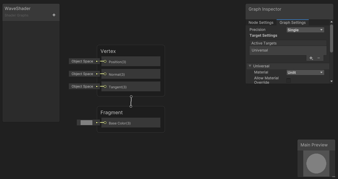
5. Double click on the shader graph asset to open it in the Editor. Note that so far all you have are empty areas to modify the vertices and fragments! (And now you know what those mean :) )
6. In the WaveShader box on the left, click the + to add two floats. Call them WaveSpeed and WaveStrength. WaveSpeed affects how quickly the vertices move, and the strength affects how much they move (or how “high” the waves are).
Update the property of these floats to match as shown in the pictures. We’ll be able to tweak these values later.
7. The shape of our waves is going to be determined by a Sine function. You might remember Sine from your high school trigonometry classes – it’s a mathematical function with an oscillating wave structure. Those two properties (repetition and shape) make trigonometric functions a key part of shaders. They also work perfectly for our needs.
But we can’t just apply this to every vertex – each part of the wave will be at a different position at a different time. To do this we require an offset for each vertex. Let’s first tackle the timing of these offsets. We can use the game Time node with our wave speed (which is in three dimensions) to determine the direction of the waves.
8. Now we can pass the output of this math, which is currently just horizontal direction and speed, into a sine function that will give us a vertical offset that we apply to the Y axis. This is also when we use the WaveStrength to scale up the verticality of the waves.
9. Okay! Now all that’s left is to apply the vertical offset to the position of the vertices. Note that this is done in Object space as opposed to World space – that is because we want the vertical movement to be relative to itself, not whatever the world up axis may be. We’ll then apply all of this to the Position of the initial Vertex node.
10. Go back to Unity, and you should now see your plane acting moving around as a wave!
On Your Own:
We’ve managed to adjust the vertices to create a wave, but right now it’s looking pretty bland. You should provide some color by connecting nodes to modify the fragment shader. Feel free to use the basics from the last guide, or just tinker around with color and variables. Note that a node’s output can be used as an input for many other nodes, so feel free to grab information from vertex nodes to inform color.
An easy way to get started is to try coloring the fragments by their vertical height, like how real waves become white when they crest.
Further Reading:
If at this point you’d like to continue learning more about shaders, here are some fantastic resources that myself and other developers have used to learn.
Book of Shaders: https://thebookofshaders.com/
The deeper, better version of this guide. Start here!
Catlike Coding: https://catlikecoding.com/unity/tutorials/
Approachable tutorials for a variety of more specific topics, including terrain generation, mesh manipulation, and applications for noise.
Shadertoy: https://www.shadertoy.com/
Platform for sharing shaders with others! Great for inspiration, and you can view the source code for every shader.
Linear algebra will go a long way: http://blog.wolfire.com/2009/07/linear-algebra-for-game-developers-part-1/
Linear algebra is more important for shader programming, but is especially helpful for vertex manipulations.
Sources and Attribution:
Images used are attributed in captions where applicable.
My acitivites borrow heavily from the following established tutorials:
Daniel Ilett’s shader graph series: https://danielilett.com/2023-09-26-tut7-3-intro-to-shader-graph/
Video version, for those who prefer:
Unity’s official shader graph introduction: https://learn.unity.com/tutorial/introduction-to-shader-graph?uv=2019.4
Render pipeline section is all based on the Real-Time Rendering textbook by Tomas Möller and Eric Haines, particularly Chapter 2. You can read that original chapter here for more detail on the process: https://cseweb.ucsd.edu//~ravir/274/15/readings/Real-Time%20Rendering/Chapter%202.pdf
Fragment and Vertex shader section is written based on the Real-Time Rendering textbook with additional explanation from Undefined Games’ post: https://www.undefinedgames.org/2019/05/13/vertex-and-fragment-shaders/
Information about common shader techniques is pulled from the respective Wikipedia articles, which are well-written to the Manual of Style and based on reputable sources: https://en.wikipedia.org/wiki/Cel_shading , https://en.wikipedia.org/wiki/Perlin_noise


